Android Map Rendering Data Flow
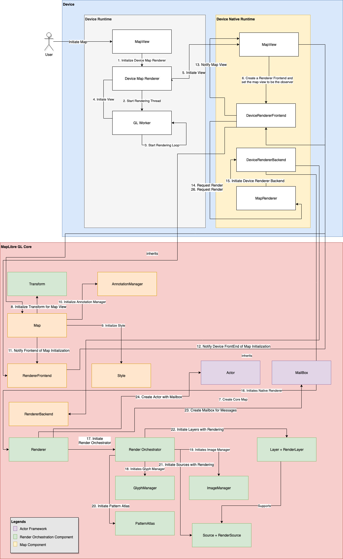
 Figure 5: Simplified data flow diagram of initializing a map in Android
Figure 5 shows a simplified data flow diagram of initializing a map. The device section of this data flow diagram is based on Android platform.
Before the map initialization request makes it to MapLibre Native Core, the request initializes a set of peer components in the platform or device runtime. Especially for Android, we have parts written in C++ using Android Native Development Kit and parts written in Java.
A map initialization starts with initializing a map in an Android View. A View occupies a rectangular area on the screen and is responsible for drawing and event handling. In this diagram this is denoted as a Map View inside the device runtime. This view is also responsible for initiating a Device Map Renderer which subsequently initializes a GL Thread worker. This thread is a render loop that takes UI events from the Android View and passes it downstream to get the rendered map.
On the native C++ side of the device code, we see a peer Map View component. This one is a wrapper class between the Android Map View and the generic Map Component. For Android, this maintains the JNI method contract established from the Java runtime. The render thread this document talked about before is seen in the form of MapRenderer. This is an Actor that passes the rendering events from the device runtime to MapLibre Native renderer.
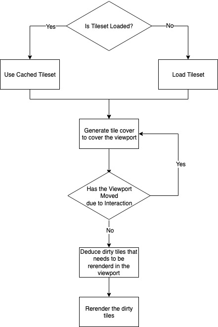
 Figure 6: Workflow of rendering tiles
Before the frame-by-frame map rendering starts with MapLibre Native renderer, the generic map component gets initialized. Rendering each frame of a map tile or initializing the map view requires a set of Transforms. Through transform basic mutations like rotation, tilt, projection is accomplished. Transforms are essential for every aspect of rendering such as resizing the viewport, setting initial map camera, changes in map camera due to tilt, zoom, and movement. Each of these operations manifest into a set of Transforms that gets applied to the to-be-rendered map tile or already rendered map tile. The Transform class noted in the diagram however does not represent a single or multitude of transformations. A Map View like other components inside MapLibre works as a state machine. The Transform class maintains the current set of global transforms applied to the map. To simplify to change the camera orientation, zoom, or pitch a Map View will update the state of the Transform class. And the Transform class will use observers to send a transform event to MapLibre Native renderer. This overall transform directive, such as change camera location from point A to point B will translate to a set of transformations deduced by the Renderer component.
Along initializing the Transform state, the Map View will also initialize the Style sub-component. The Style component here also follows a state machine-esque behaviour. It holds the current state of used Styles for the Map View along with layers, glyphs, and sources. A change in style or initialization of style translates to re-loading the Glyph Atlas, Sources, and Layers. A Glyph Atlas is a combined image all glyphs. The renderer slices the necessary glyph by bounding boxes whenever necessary. Different sources are loaded differently. For Tilesets, the tile data is loaded but not rendered right away. For client provided data sources such as GeoJSON, the data is loaded from the file source or code. Then these sources are organized into layers dictated by the style and the layers are sent for rendering through the actors.
The key philosophy of rendering tiles is tiles are rendered layer by layer. A collection of tiles is called a tile set. To optimize tile rendering, MapLibre Native only renders dirty tiles. A dirty tile is a tile rendered in the viewport that has changed due to user interaction. To initiate this process, MapLibre Native loads the tileset to be rendered first. In a rendering request, if the tileset is already loaded, MapLibre Native will use a cached tile set.
The next decision to make here is which tiles are to be rendered on the viewport. To deduce this, MapLibre Native translates the device viewport coordinates1 to a tile cover. A tile cover loads all the tiles that will rendered to current viewport. If the viewport already has all the tiles that is needed to be rendered by the deduced tile cover, there are no dirty tiles. If the tile cover somehow has a single or all new tiles to be rendered in the viewport, the existing tiles displayed in the viewport are deduced to be dirty. And only these tiles are replaced instead of a complete re-render.
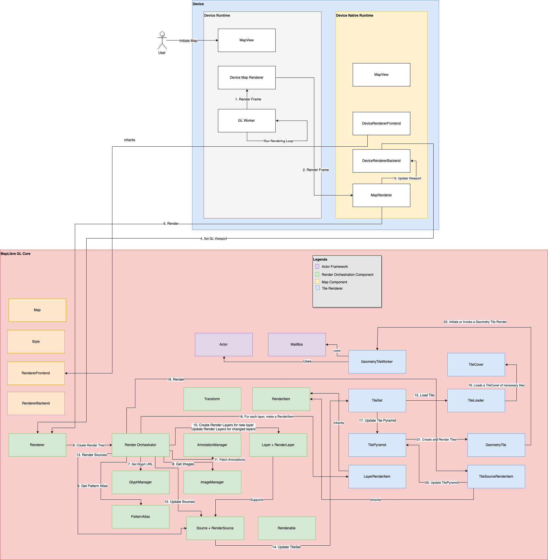
Moving to the render flow now. The render flow is depicted in Figure 7. The diagram introduces a new component block named a Tile Renderer. These diagrams might look verbose but in reality, they are a simplified version of the actual code flow.
The render workflow stays the same as the initialization workflow up to reaching the Render Orchestrator. This time instead of initializing the render orchestrator, the flow uses the render orchestrator to create a Render Tree. A render tree is a tree of to-be-rendered items in order. This includes rendering items from layers, sources, line atlas, and pattern atlas. A render orchestrator does not render anything by itself. It orchestrates render items for the renderer.
In the render loop ran by the Renderer, each render request ends in creating a new render tree, and the render function. The render function uses a glyph manager for fetching glyphs and font stacks that contains said glyphs. Sources and Layers are translated to RenderSource and RenderLayer objects.
For the sake of restating, a layer is composed of a set of sources.
 Figure 7: Simplified data flow diagram of rendering map tiles
A RenderSource is produced from a single source that has an internal update method. This method produces the tile pyramid to render for said source if the source is a TileSource. For brevity, this document only talks about tile sources. There are other types such as GeoJSON sources. They work in a similar manner as the tile source.
-
Viewport coordinates are derived from the coordinate system of the device screen. Anything rendered inside a unit cube of local space is translated to screen space of actual pixels. The tiles are rendered in a local space before rendered back to screen. We will see more about that in Coordinate System section. ↩